1. TEST
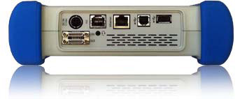
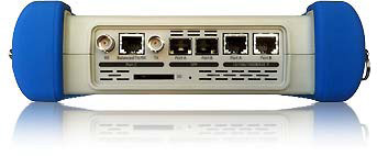
1.1 CONNECTORS
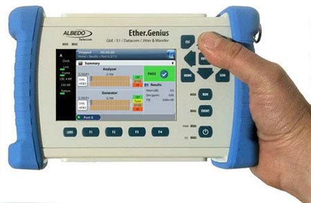
- Operation over two Gigabit Ethernet physical interfaces (PortA, PortB) based either on SFPs or RJ45 connectors.
- Port C: Unbalanced (BNC) 75Ω / balanced (RJ45) 120Ω.
- Smart Serial universal datacom connector for the DTE and DCE (all datacom interfaces).
- Analogue voice frequency audio port.
1.2. OPERATION MODES
- Ethernet Endpoint operation: The equipment generates and receives Ethernet PCS codes and Ethernet frames.
- IP Endpoint operation: The equipment generates and re-ceives IPv4 datagrams.
- Through operation: Traffic is forwarded between port A and portB.
- Ethernet L1 Endpoint operation: The equipment generates PCS codes and L1 BER measurement patterns.
- E1 modes: E1 monitor, E1 endpoint, E1 mux, E1 demux, E1 through, analogue.
- Datacom modes: Datacom endpoint, Datacom monitor.
1.3. CLOCK REFERENCES
- Internal time reference better than ±2.0 ppm. Optional inter-nal reference better than ±0.2 ppm.
- Ethernet input through Port A or Port B over any valid elec-trical / optical synchronous Ethernet interface.
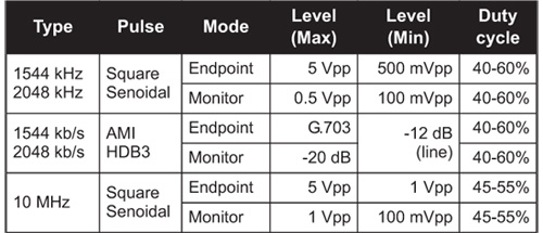
- 10 MHz, 2048 Mb/s, 2048 MHz, 1544 Mb/s, 1544 MHz input through Port C (balanced or unbalanced) or through DTE port (balanced interface, RJ-48 connector adapter).
- One-pulse-per-second (1pps) synchronization input through DTE port (balanced interface, RJ-48 connector adapter).
- 2048kHz reference output through Port C (balanced or un-balanced), 1pps through DTE port (balanced interface, RJ-48 connector adapter).
Table 1. Clock reference input levels
2.ETHERNET
2.1.ETHERNET PHY
- Supported interfaces (SFP): 10BASE-T, 100BASE-TX, 100BASE-FX, 1000BASE-T, 1000BASE-SX, 1000BASE-LX, 1000BASE-ZX.
- Supported interfaces (RJ-45 ports): 10BASE-T, 100BASE-TX, 1000BASE-T.
- On/off laser control for optical interfaces.
2.1.1 Auto-Negotiation
- Negotiation of bit rate. Allow 10Mb/s, allow 100Mb/s, allow 1000Mb/s.
- Negotiation of Master and Slave roles in the 1000BASE-T interface.
- Ability to disable auto-negotiation and force line settings.
2.1.2 Power over Ethernet
- PoE (IEEE 802.3af-2003) and PoE+ (IEEE 802.3at-2009) detection.
- PoE interfaces: 10BASE-T, 100BASE-T and 1000BASE-TX through attached RJ-45 ports A and B.
- PoE pass-through when the equipment is configured in transparent (through) operation mode.
2.2. SYNCHRONOUS ETHERNET
- Supported interfaces: 100BASE-TX and 1000BASE-T through the attached RJ-45 ports. 1000BASE-SX, 1000BASE-LX, 1000BASE-ZX and 1000BASE-BX through external SFP.
2.2.1 Operation
- Analysis of synchronous Ethernet signal in Ethernet end-point, IP Endpoint and Through modes, generation of syn-chronous Ethernet signal in Ethernet endpoint and IP Endpoint modes. Transparent synchronous Ethernet pass-through in Through mode.
- Configuration of internal, external or recovered clock in Ethernet interfaces.
- Fixed freq. offset generation on transmitted signals with maximum value of ±125 ppm (resolution 0.001ppm) as per ITU-T O.174 (11/2009) 8.2.1.
2.2.2 Analysis
- Measurement of the line frequency (MHz), frequency offset (ppm) and frequency drift (ppm/s) as specified in ITU-T O.174 (11/2009) clause 10.
2.3. ETHERNET MAC
- Frame formats: DIX, IEEE 802.1Q, IEEE 802.1ad.
- Support for Jumbo frames with MTU up to 10kB.
- Setting of source and destination MAC addresses. Destina-tion addresses can be configured as a single value or as a range
- Setting of the Type/Length value.
- Configuration of the VID and priority codepoint in VLAN modes.
- In Q-in-Q/IEEE 802.1ad modes, configuration of the S-VLAN VID, DEI and priority codepoint. Configuration of the C-VLAN VID and priority codepoint.
- Configuration of the frame size.
2.4. MPLS
- MPLS generation and analysis in IP Endpoint mode. MPLS analysis in IP through mode.
- Support of a single and double label stack (Top and Bottom labels). Label formatting follows RFC 3032.
- Configuration of the TTL, traffic class and label value for Top and Bottom MPLS headers.
2.5. IPV4
- Configuration of source and destination IPv4 addresses. Destination addresses can be configured as a single value or as a range.
- Configuration of DSCP CoS labels, TTL and transport proto-col.
- If transport protocol is UDP, support of UDP frame with source and destination port configuration.
2.6. TRAFFIC GENERATOR
- Generation over 8 independent streams. Each stream has its own specific bandwidth profile and payload/pattern con-figuration.
2.6.1 Bandwidth Profiles
- Generation modes: Continuous, Periodic burst, Ramp and Random.
2.6.2 Test Patterns and Payloads
- Layer 2-4 BER test patterns: PRBS 211-1, PRBS 215-1, PRBS 220-1, PRBS 223-1, PRBS 231-1 along with their in-verted versions and user (32 bits). These patters apply to stream 1 only.
- Test payload for SLA tests.
- All zeros test pattern.
- NCITS TR-25-1999 RPAT, JPAT and RPAT for L1 BER tests.
- IEEE 802.3, Annex 36A HFPAT, LFPAT, MFPAT, LCRPAT, SCRPAT for L1 BER tests.
2.7. EVENT INSERTION
- Insertion of TSE, FCS errors, Undersized frames and IPv4 checksum errors.
- Insertion modes: Single, burst, rate and random.
2.8. FILTER
- Up to 8 simultaneous filters can be applied to the traffic.
- The equipment supports a generic filter which can select frames by using a 16 bit mask and an arbitrary offset de-fined by the user.
2.8.1 Ethernet Selection
- By source and destination MAC addresses. Selection of MAC address sets with masks.
- By Type/Length value with selection mask.
- By C-VID and S-VID with selection mask.
- By service and customer priority codepoint value with selec-tion mask.
2.8.2 MPLS Selection
- Separated filters to account for the top and bottom MPLS headers.
- Filtering by label value.
- Filtering by traffic class.
2.8.3 IPv4 Selection
- Selection by IPv4 source or destination address. It is possi-ble to select address sets by using masks.
- Selection by protocol.
- Selection by DSCP value.
2.8.4 IPv6 Selection
- Selection by IPv6 source or destination address (or both at the same time). It is possible to select address sets by using masks.
- Selection by IPv6 flow label.
- Selection based on the next header field value.
- Selection by DSCP value.
2.8.5 UDP Selection
- Selection by UDP port. Either as a single value or a ranges.
2.9. PHY RESULTS
2.9.1 Cable Tests
- Optical power measurement (transmitted and received pow-er) over compatible SFP transceivers.
- Inactive links: Open/short fault indication and distance to fault in metres (accuracy: 1m, range 100m).
- Active links: current local port MDI/MDIX sta-tus, .cable wiring (straight, crossed), po-larity (positive, negative) pair skew (1000BASE-T only), crosstalk.
2.9.2 Auto-Negotiation
- Bit rate and duplex mode.
- Master/slave role in 1000BASE-T in-terfaces.
2.9.3 SFP
- SFP presence, current interface, vendor, and part number.
2.9.4 Power over Ethernet
- Type of PoE: PoE (IEEE 802.3af), PoE+ (IEEE 802.3at), none.
- PoE voltage between pairs 1-2 / 3-6 and 4-5 / 7-8 in end-point test. Voltage and current in pairs 1-2/3-6 and 4-5/7-8 in through mode.
2.10. FRAME ANALYSIS
- Support of local one-way (port A-port B) and two-way (port A-port A) test modes.
- Separate traffic statistics for Port A and B.
2.10.1 Ethernet Statistics
- Frame counts: Ethernet, VLAN, IEEE 802.1ad frames, Q-in-Q frames, control frames, pause frames.
- Frame counts: unicast, multicast and broadcast.
- Basic error analysis: FCS errors, undersized frames, over-sized frames, jabbers.
- Frame size counts: 64 or less, 65-127, 128-255, 256-511, 512-1023, 1024-1518, 1519-1522, 1523-1526 and 1527-MTU bytes.
2.10.2 MPLS Statistics
- MPLS stack length: minimum, maximum.
2.10.3 IP Statistics
- Packet counts: IPv4 packets, IPv6 packets.
- Packet counts: unicast, multicast and broadcast.
- UDP packets, ICMP packets.
- IPv4 errors, IPv6 errors.
- UDP errors.
2.10.4 Bandwidth Statistics
- Ethernet traffic statistics expressed in bits per second, frames per second and a percentage of the nominal channel capacity.
- Unicast, multicast and broadcast traffic figures expressed in frames per second units.
- IPv4 and IPv6 statistics (frames per second, bits per second and percentage).
- UDP traffic (frames per second, bits per second and per-centage).
2.10.5 SLA Statistics
- Multistream SLA analysis.
- Delay statistics: ITU-T Y.1563 FTD (current, minimum, max-imum, and mean values).
- Delay variation statistics: ITU-T Y.1563 FTD (standard devi-ation), ITU-T Y.1563 FDV (peak), RFC1889/RFC3393 jit-ter (current, maximum and mean values).
- Frame loss: ITU-T Y.1563 FLR.
- Duplicated packets, out -of -order packets (RFC5236).
- Availability statistics: SES and ITU-T Y.1563 PEU.
2.10.6 BER
- Bit error count, seconds with errors, bit error ratio (BER).
- Pattern losses, pattern loss seconds.
2.10.7 Network Exploration
- Top talkers statistics: Displays the 16 most common source MAC/IPv4/IPv6 addresses.
- Top VID (IEEE 802.1Q) or C-VID (IEEE 802.1ad): Displays the 25 most common VID/C-VID tags.
2.11. AUTOMATIC TESTS
- The equipment supports automatic normalized tests defined in IETF RFC2544 and ITU-T Y.1564 (eSAM).
- Support of local one-way (port A - port B) and two-way (port A - port A) tests.
- Support of Ethernet and IP test modes.
2.11.1 IETF RFC2544 Test
- Support of RFC-2544 throughput, frame-loss, latency, back-to-back and recovery time tests.
2.11.2 eSAM Test
- Testing of up to eight services (non-colour aware mode) or up to four services (colour aware mode).
- Configuration of the CIR and EIR for each service.
- Configuration tests (CIR, EIR and policing) with FTD, FDV, FLR results for each service.
- Performance test with FTD, FDV, FLR and availability re-sults for all services.
2.12. PORT LOOPBACK
- •Layer 1-4 loopback.
•Loop frames matching current filtering conditions or loop all frames in layer 2-4 loopbacks.
•Loop controls for broadcast and ICMP frames.
2.13. PING AND TRACE-ROUTE
- Generation of on demand ICMP echo request (RFC792) messages with custom destination IP address, packet length and packet generation interval.
- Analysis of ICMP echo reply (RFC792) messages with measurement of round trip time and lost packets.
- Analysis of ICMP Time-To-Live Exceeded and ICMP Port unreachable replies received in the trace-route test.
2.14. PTP / IEEE 1588
- Operation: IEEE 1588-2008 transparent, non-intrusive mon-itoring in Ethernet Endpoint, IP endpoint and Through modes.
- Support of hardware-assisted decoding of Precision Time Protocol (PTP) as defined in IEEE 1588-2008.
- Encapsulations: PTP over UDP over IPv4 as defined in IEEE 1588-2008 Annex D, PTP over IEEE 802.3 / Ethernet defined in IEEE 1588-2008 Annex F.
2.14.1 Results
- Presentation of peer clock details: Master identity, Grand-master identity, Grandmaster priority 1, Grandmaster priority 2, Grandmaster clock class, Grandmaster clock accuracy, Grandmaster clock variance, Grandmaster time source.
- TX and RX PTP frame counts classified by frame type.
- Sync Inter Arrival Delay (IAD) analysis: average and cur-rent.
- Sync Packet Total Delay (PTD): standard deviation, range.
- Sync Packet Delay Variation (PDV): current, maximum, av-erage.
- Frequency offset between the master and the local clock (ppm).
2.15. PROTOCOLS
- ARP (IETF RFC826).
- DNS (IETF RFC1034, RFC1035).
- DHCP (client side) (IETF RFC2131).
- Trace-route application using UDP.
3. ITU-T G.703/E1
3.1. LINE
- Configurable input impedance: nominal line impedance, PMP 20dB, PMP 25dB, PMP 30dB, high impedance (> 1000 Ω).
- Configurable output frequency offset within ±25,000ppm around the nominal frequency.
- Line codes: HDB3, AMI.
- Input Level: From 0dB to -45dB.
- Pulse mask compliance: ITU-T G.703.
- Jitter compliance: ITU-T G.823.
3.2. FRAME
- 2048kb/s unframed, ITU-T G.704, ITU-T G.704 CRC, ITU-T G.704 CAS, ITU-T G.704 CRC + CAS.
- Generation of custom NFAS spare bits (ITU-T G.704 frame with CRC-4 multiframe).
- CAS A, B, C, D bit generation for each voice channel. Gen-eration of CAS multiframe spare bits (ITU-T G.704 frame with CAS multiframe).
3.3. TEST PATTERNS AND SIGNALS
- PRBS9 (ITU-T O.150, O.153), PRBS11 (ITU-T O.150, O.152, O.153), PRBS15 (ITU-T O.150, O.151), PRBS20 (ITU-T O.150, O.153), PRBS23 (ITU-T O.150, O.151), PRBS9 inverted, PRBS11 inverted, PRBS15 inverted, PRBS20 inverted, PRBS23 inverted, all0, all1.
- User configurable 32 bit word.
- Tone (from 10 Hz to 4000Hz, from +6dBm to -60dBm).
- External signal: Analogue, 64kb/s G.703/E0 (AT-2048 on-ly), data communications interface.
3.4. ANALYSIS
- Analogue: Line attenuation (dB), frequency (Hz), frequency deviation (ppm), round trip delay (μs). Analogue results in-clude pass / fail indications.
- Defects: LOS, LOF, AIS, RAI, CRC-LOM, CAS-LOM, MAIS, MRAI, LSS, All 0, All 1.
- Anomalies: Code, FAS error, CRC error, REBE, MFAS error, TSE, Slip.
- Live and history LEDs for all Defects and Anomalies.
- ITU-T G.821 performance: ES, SES, UAS, DM. ITU-T G.821 results include pass / fail indications.
- ITU-T G.826 performance: ES, SES, UAS, BBE (near and far end statistics). ITU-T G.826 results include pass / fail in-dications.
- ITU-T M.2100 performance: ES, SES, UAS, BBE (near and far end statistics). ITU-T M.2100 results include pass / fail indications.
- ITU-T G.711 occupation map and time slot analysis: maxi-mum code, minimum code, average code, time slot level and frequency.
- CAS A, B, C, D bit analysis.
- Drop to external output: Analogue, 64kb/s codirectional (PortA only), data communications inter-face.
3.5. EVENT INSERTION
- Physical: AIS, LOS.
- Frame: FAS error, CRC error, MFAS error, REBE, LOF, MAIS, CAS-LOM, RAI, MRAI, CRC-LOM.
- Pattern: TSE, Slip, LSS, All0, All1.
- Insertion modes: Single (anomalies), rate (anomalies), con-tinuous (defects), burst of M (defects), M out of N (defects).
3.6. JITTER AND WANDER GENERATION FUNCTION
- Modulation waveform: sinusoidal.
- Modulation frequency range: 1 μHz to 100 kHz.
- Modulation frequency resolution: 0.1Hz (jitter), 1 μHz (wan-der).
- Modulation amplitude: 0 – 1000 Uipp. Maximum depends on modulation frequency.
- Modulation amplitude resolution: 1 mUIpp or 1/104 config-ured value.
- Modulation amplitude accuracy: better than O.172.
- Smooth amplitude changes in jitter range (10 Hz – 100 kHz).
- Intrinsic jitter < 10 mUIpp.
3.7. JITTER ANALYSIS FUNCTION
- Closed loop phase measurement method. Reference fre-quency not required.
- Modulation frequency range: 0.1Hz to 100kHz (locking time 10s), 1Hz to 100kHz (locking time 1s), 10Hz to 100kHz (locking time < 1s).
- Modulation amplitude: 0 to 1000UIpp (single range) (maxi-mum amplitude depends on modulation frequency).
- Modulation amplitude resolution: 1 mUIpp.
- Measurement accuracy: better than ITU-T O.172.
- Jitter measurement results: peak to peak jitter, RMS jitter, maximum jitter (user reseteable), hits detection and count (user selectable threshold).
- Jitter measurement observation time: 1s, 10s, 60s.
- Measurement selectable filters: LP (f < 100kHz), LP+HP1 (20Hz<f<100kHz), LP+HP2 (18kHz < f < 100kHz), LP+RMS (12kHz < f < 100kHz).
3.8. WANDER ANALYSIS FUNCTION
- Open loop measurement method. Reference frequency re-quired.
- Modulation frequency range: 1μHz to 10Hz.
- Wander sampling frequency: 50Hz.
- Modulation amplitude: 0 to ±2s (single range).
- Modulation amplitude accuracy: 2ns.
- Instantaneous: TIE, frequency offset, frequency drift.
- Statistics results: TIE, MTIE, TDEV.
- Statistics range: 102, 103, 104, 105, 106s.
- Built in, real time statistics analysis.
3.9. PULSE MASK ANALYSIS
- Operation modes: Eye diagram or continuous run.
- Measurement of pulse width, rise time, fall time, level, over-shoot and undershoot (positive and negative pulses).
- Pass / fail indication for compliance with ITU-T G.703 E1 mask.
4. ITU-T G.703/E0
4.1. CONNECTOR
4.2. FEATURES
- Bit rate Nx64kb/s (N from 1 to 4).
- Test pattern generation and analysis over co-directional in-terfaces.
- Defect insertion and analysis: LOS, AIS, LSS, All0, All1.
- Anomaly insertion and analysis: TSE, Slip.
5. DATA COMMUNICATIONS
5.1. CONNECTORS
- Smart Serial universal datacom connector for the DTE and DCE (all interfaces).
5.2. INTERFACES
- V.24/V.28 asynchronous (RS-232) from 50b/s to 128kb/s.
- V.24/V.28 synchronous (RS-232) from 50b/s to 128kb/s.
- X.21/V.11 from 50b/s to 2048kb/s.
- V.35 from 50b/s to 2048kb/s.
- V.36 (RS-449) from 50b/s to 2048kb/s.
- EIA-530 from 50b/s to 2048kb/s.
- EIA-530A from 50b/s to 2048kb/s.
5.3. TESTS
- Operation: DTE emulation, DCE emulation and full duplex monitor.
- Test pattern generation and analysis over a datacom inter-faces.
- Logic analyser capability.
- Defects: LOC, AIS, LSS, All 0, All 1.
- Anomalies: TSE, Slip.
- Analogue: Line attenuation (dB), frequency (Hz), frequency deviation (ppm).
6. FRAME RELAY MONITORING
6.1. INTERFACES
- X.21/V.11 from 50b/s to 2048kb/s.
- V.35 from 50b/s to 2048kb/s.
- V.36 (RS-449) from 50b/s to 2048kb/s.
- EIA-530/EIA-530A from 50b/s to 2048kb/s.
6.2. SETTINGS
6.3. EVENTS
- Long frames, short frames.
- Alignment errors.
- FCS errors •Frame abort count.
6.4. STATISTICS
- Bandwidth statistics
- Maximum and minimum frame size.
- Frames with FECN, BECN and DE.
- Active DLCI list.
- LMI frame count.
7. IEEE C37.94
- Transmission media follows specifications of IEEE C.37.94 section 7. •Unframed or framed operation. Frame structure follows IEEE C37.94 section 4.1.
- Configurable bit-rate between 64kb/s and 768kb/s in steps of 64kb/s.
- Transmission clock: Recovered or internally synthesized.
- Measurement of: frequency, frequency offset, latency and received bit rate.
- Event detection and insertion: LOS, AIS, FAS, RAI (yellow), LSS, ALL0, ALL1, Slip, TSE.
- BER and ITU-T G.821 performance test.
8. ANALOGUE TEST
- Tone Generation (from 10 Hz to 4000Hz, from 0dBm to -60dBm).
- Level and frequency.
- ITU-T G.711 analysis: maximum code, minimum code, aver-age code.
9. USER INTERFACE
- Direct configuration and management in graphical mode us-ing the keyboard and display of the instrument.
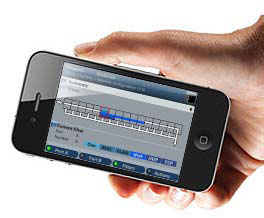
- Remote access for configuration and management in graph-ical mode from remote IP site thought the patform Ethernet interfacel.
- File management and download through web interface.
10. PLATFORM
- Operation time with batteries (LiPO): 8 - 10 hours.
- Battery recharge time (LiPO): 4 hours.
- Operational range: -10oC to +50oC.
- Operation humidity: 10% - 90%.
- IP rating: 54.
- Configuration and report storage and export through at-tached USB port.
- TFT colour screen (480 x 272 pixels).
- Dimensions: 223mm x 144mm x 65mm.
- Weight: 1.2kg (with rubber boot).
|